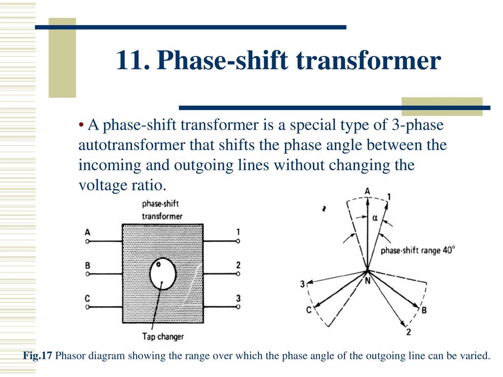
Phase Shifting Transformers PST are used to control or block certain flows of real power through phase angle regulation across the device. And so the phase shift angle range used in the model is the no-load phase shift angle range which relates the source terminal voltage ei to the winding 2 terminal voltage ej of the ideal transformer.

First of all delta-wye transformers dont always make a 30 electrical shift.
Transformer phase shift angle. We know that across a delta-wye star or wye- delta transformer there will a 30-degree phase shift between line voltages. With this there are two options. Delta could lead the wye side by 30 degree or wye side could lead the delta by 30 degrees.
The theory of phase-shifting transformer is the flow of power throughout a transmission line can be proportional toward the sine of the disparity within the phase angle of the voltage among the end of transmitter the receiver of the transmission line. So the phase angle can be shifted within the ends of the transmitter and receiver of a line. Phase Shifting Transformers PST A Phase Shifting Transformer PST is a specialised type of transformer typically used to control the flow of active power on three-phase electric transmission networks.
It does so by regulating the voltage phase angle difference between two nodes of the system. The principle relies on a phase shifted voltage. Depending on how the high side and low side windings get wound on the core the transformer shifts the phase angle accordingly explained in detail in this paper by Basler.
Source vector getting shifted in phase angle as you go through a transformer. Phase shift 360 time wave period. Phase shift is in degrees and time is the time difference.
And you dont want to find the angle of each signal rather you want to find the phase angle difference between the two sine waves. Phase Shifting Transformers PST are used to control or block certain flows of real power through phase angle regulation across the device. Its functionality is crucial to special situations such.
Transformer winding phase angle shift dpc Electrical 8 Jan 03 1651 For a transformer built to ANSI standards the low side should lag the high side by thirty degrees. Special power transformers are power transformers which have phase angle shift different from 30 o or a multiple of 30 4. Typical example is 24-pulse converter transformer with additional phase angle shift Θ of 75o.
Such special transformers typically have three windings but sometimes even up to five windings 1. There is no phase angle shift in Delta Delta or Wye-Wye transformer. However there is 30 degree phase angle shift in Delta-Wye transformer.
Many articles take that as a fact without any explanation. Articles also state that high voltage side leads the low voltage side by 30 degree. In addition to the transferred power the phase-shift angle is also important.
A phase-shift angle of 20 means that the PST has to be designed for 348 of the throughput power and an angle of 40 would require 684. First of all delta-wye transformers dont always make a 30 electrical shift. Thats just the ANSI standard.
Therere delta-wye transformers with a phase shift of 150. If you dont know what vector groups are stop reading this. Read Chapmans textbook Electric Machinery Fundamentals or any other textbook that helps you or you can read this webpage which is a pleasant introduction to the topic.
Phase shifting transformers Definition. A phase shifting transformer see fig1 is a special type of system intertie transformers which Control the power flow through specific lines in a complex power transmission network by providing the possibility to insert a voltage with an arbitrary phase angle in the power system. Transformer equal to the load terminal voltage of the phase-shifting transformer.
And so the phase shift angle range used in the model is the no-load phase shift angle range which relates the source terminal voltage ei to the winding 2 terminal voltage ej of the ideal transformer. A 30 phase shift wouldnt produce the reported voltages. Reverse phase sequence on one of the transformers as noted by Kiribanda would.
This results in a 60 phase shift on the secondary. This is probably the cause - two phases are reversed on the primary of one of the transformers. In other words the phase shift from primary to secondary will be zero degrees.
On the other hand if the dots on each winding of the transformer do not match up the phase shift will be 180 between primary and secondary like this. Primary red to dot secondary black to dot. Transformer impedance correction tables are used to specify how the impedance of the transformer should change with the phase angle.
If this number is 0 no impedance correction table is associated with the transformer and the impedance of the transformer will thus remain fixed as the phase angle changes. The magnitude and direction of phase shift depend on the transformer group and allocation of phase references. The phase shift of zero sequence quantities needs not to be considered in star-delta transformer because the zero sequence currents do not flow in lines on the delta-connected side.
In power grids phase-shifting transformers provide active power flow control. By enforcing or blocking loads they not only improve the stability and flexibility of grids but also help grid operators get the most out of existing hardware. Phase-shifters are available in a range from 2000 MVA and 765 kV.