Most Parallel Ports implemented in ASIC can sink and source around 12mA. My red multimeter probe on say pin3 and then watch the voltage change as I fiddle with the x axis.

The maximum voltage on the output side is 30V.
Parallel port voltage output. In this way the parallel port automatically powers DA stage of the circuit which gives the output voltage directly. The maximum current the circuit takes is about 1 mA from datapin D7 and the total power consumption is less than 2 mA. This is well in the range what.
This means that they put out ideally 0V when they are in low logic level 0 and 5V when they are in high logic level 1. In real world the voltages can be something different from ideal when the circuit is loaded. The output current capacity of the parallel port is limited to only few milliamperes.
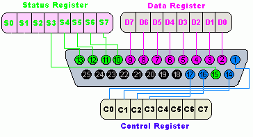
12 rader The PC parallel port usually consists of 25 pins in a DB-25 connector. I am wanting to re-purpose an old laptop computer to use its parallel port LPT printer port to output a 5V0V signal on one of the data pins. The load requires about 9 mA at 5V.
Parallel port ideally gives TTL logic 0low and 5V high. But my port gives 33V high. I have designed my controlcircuit assuming the high to be 5V.
Is there a way to regulate the 33V to 50V so that I can still use the existing control circuit. The output of the Parallel Port is normally TTL logic levels. The voltage levels are the easy part.
The current you can sink and source varies from port to port. Most Parallel Ports implemented in ASIC can sink and source around 12mA. The standard parallel port is capable of sending 50 to 100 kilobytes of data per second.
Lets take a closer look at what each pin does when used with a printer. Pin 1 carries the strobe signal. It maintains a level of between 28 and 5 volts but drops below 05 volts whenever the computer sends a byte of data.
The parallel port usually comes as a 25-pin female port and it is commonly used to connect printers to a computer. Many geeks also use it to connect their own devices to their PCs. There is a few more things to remember when using a PCs Parallel Port.
It can load only 25mA and 25 volts. Parallel port from a PC. A PC Parallel port should be able to drive the inputs to this relay module.
A typical output of one of the DB0 to DB7 lines from the PC Parallel port would be able to turn on the relay coil when the port bit is at a low level and the proper Opto-Coupler Relay coil voltages are supplied to the relay module. The LPT ports 5V output signals dont easily support the low-voltage logic required to increase battery life and achieve longer data-acquisition times. Because dynamic power consumption for a microprocessor or clocked circuit is predominately a function of voltage P CV²f logic systems that operate off the parallel port at below 5V can substantially conserve power.
Testing parallel port output with a multimeter. Hello Guest it is April 24 2021 060322 AM. I have a db25 cable hooked up to my parallel port with a breakout on the end.
I have no motors. My red multimeter probe on say pin3 and then watch the voltage change as I fiddle with the x axis. You ask me to post my xml.
I dont know. The problem is not associated to power on the parallel port because all of our boards can take 33 or 5vdc signals with power as low as 005mA. The output is always 5vdc at 24mA at least.
The operating frequency can be from 100khz to 4Mhz depending on the model. The C10 can do 4Mhz without significantly altering the original wave form. The maximum voltage on the output side is 30V.
The input to output isolation can handle up to 1500V voltage. You connect the input side to the parallel port output pin you want to use for the controlling. Then you connect the input - side to parallel port ground pin.
The output side is connected to the circuit to be controlled at right polarity. Be careful with that stuff - the parallel ports expected voltage is very small and very sensitive. Im talking about the hardware part of the issue here.
I made this with C a dozen or so years ago but that was before the OSes really clamped down on hardware IOs. Diadem Dec 30 09 at 1408. The only connection between the PCs parallel port and the electrical devices controlled by the phototransistors is the light beam emitted by the light-emitting diode.
When one of the parallel port output pins assumes a high state it sends 5 volts to its respective. The output pins of the parallel port are TTL level output pins. This means that they put out ideally 0V when they are in low logic level 0 and 5V when they are in high logic level 1.
In real world the voltages can be something different from ideal when the circuit is loaded.