1 Test the motor de-energized by using a properly working voltmeter. Motor windings resistance test.

Transformer winding resistance measurements are obtained by passing a known DC current through the winding under test and measuring the voltage drop across each terminal.
How to measure motor winding resistance. This video takes a look at ohmmeters and how to measure winding resistance in a submersible motor. Why is this important. So you can know the condition of yo.
You should regularly check the resistance of the windings in a motor to be sure its operating at peak ability. Turn on the digital multimeter. Turn the measurement setting dial on the multimeter to resistance.
The resistance setting is designated by the capital Greek letter omega. Minimum motor insulation resistance of the winding to the ground is measured with 500 V DC. The winding temperature must be 25C - 15C.
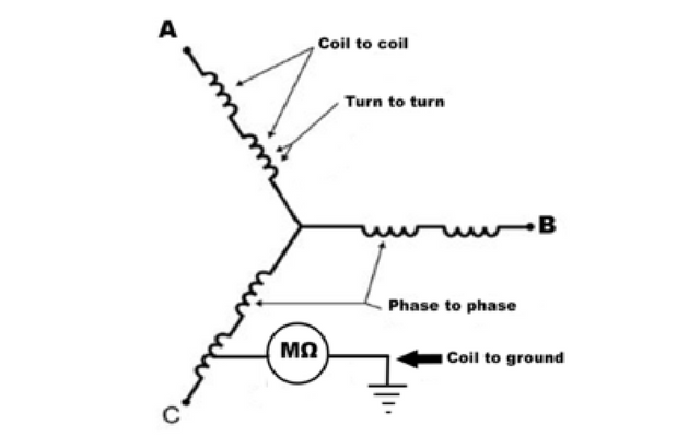
Maximum insulation resistance should be measured with 500 V DC with the windings at an operating temperature of 80-120C depending on the motor type and efficiency. Check the motor winding resistance or ohms reading using a multimeter or ohmmeter for phase to phase terminal U to VV to WW to U. The ohms reading for each winding must be the same or nearly the same.
Remember that the three phases. For most common resistance measurements you can use a regular multimeter set to the ohms Ω scale. However the windings in large motors have low resistance and are very inductive.
The tester must therefore safely inject sufficient test current at a more significant test voltage to measure the stator winding safely and timely. Open the cover of the conduit box. Before measuring eliminate all links in the conduction box.
Measure resistance for each winding the resistance between 2 distinct winding and resistance between twisting and motors frame. Resistances Of Three Phase Motor Winding needs to be the same - 5. Resistance involving two winding and winding framework ought to be more than.
Measurement Minimum insulation resistance of the winding to ground is measured with 500 V DC. The winding temperature should be 25C. Maximum insulation resistance should be measured with 500 V DC with the windings at a operating temperature of 80.
This test provides a DC voltage to the motor winding and measures how much current flows through the insulation to ground. 1 Test the motor de-energized by using a properly working voltmeter. 2 Place both instrument test leads to ground and verify a solid connection to ground of the instrument lead.
The winding resistance can be measured with 2 wires from the measurement device connected to each end of the DUT. In this case the resistance measured will include the resistance of the leads from the measurement device to the DUT. Our 4-wire resistance measurement uses Kelvin clamps for improved accuracy.
Could be a loose connection disconnect the links check all terminals measure the resistance of each individual winding preferred cold and they should be near enough the same on a cheapo meter. There may be a small difference depending on how the windings are laid down. For a 15Kw you will be down in the less than 5 Ohms range.
Motor winding resistance test uses the Four-wire Kelvin measurement method. It provides the best possible measurement results since it ensures that the resistance of the connecting current cables is not included in the measurement. The test current is passed through the windings using the high current cables.
An overview of two basic winding resistance tests one can perform in the shopFor expert repair guidance or more information call 800-551-4420 or httpwww. Using Ohms law the resistance is calculated in µΩ micro Ohms or mΩ milli Ohms by the winding analyzer. For a 3-phase motor 3 resistance measurements are normally done between the phases and the balance or imbalance between the 3 measurements is calculated and displayed along with the measurement values.
Accurately measuring the resistance. If the resistance is less than 5 ohms use a milli-ohm meter or bridge device. 2 Circuits 3 Leads Each If the motor has 2 independent circuits of 3 leads each it is either a part-winding start or a 2-winding motor.
Surge test each set of 3 leads separately. If the surge test pattern for each 3-lead circuit has two good patterns and 1 bad. For a three phase motor insulation resistance is usually measured between each motor winding or phase and between each motor phase and motor frame earth using an insulation tester or megger.
Set the voltage setting of the insulation resistance tester to. Transformer winding resistance measurements are obtained by passing a known DC current through the winding under test and measuring the voltage drop across each terminal. Modern test equipment for this purposes utilizes a Kelvin bridge to achieve results.
You might think of a winding resistance test set as a very large low-resistance ohmmeter DLRO. The transformer winding resistances can be measured by current voltage method. In this method of measurement of winding resistance the test current is injected to the winding and corresponding voltage drop across the winding is measured.
By applying simple Ohms law ie. R x V I one can easily determine the value of resistance. Motor windings resistance test - YouTube.
Motor windings resistance test. If playback doesnt begin shortly try restarting your device.