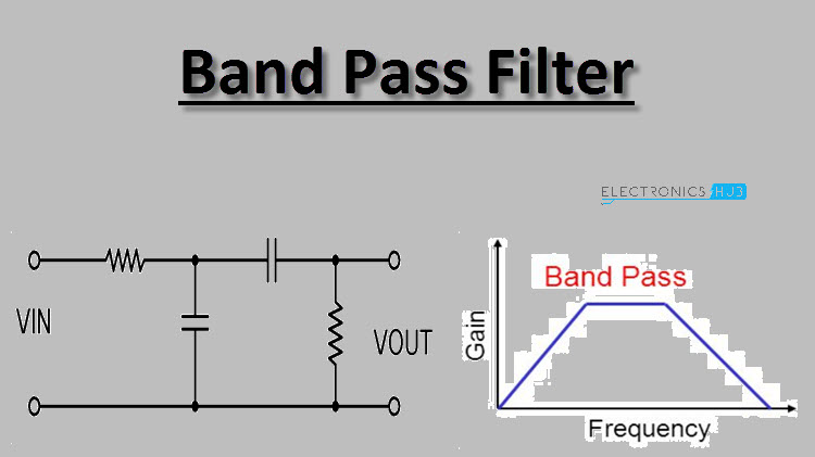
All lower and higher frequency components are attenuated or stopped. A band pass filter also known as a BPF or pass band filter is defined as a device that allows frequencies within a specific frequency range and rejects attenuates frequencies outside that range.

B Design the filter using the Kaiser window.
Fm bandpass filter design. FM Bandpass Filters Jampro Antennas also provides a range of FM Bandpass Filters ranging from 500w to 35000 watts. Designed to provide superior performance for low to high power transmitter systems in a modular configuration. Filters with either two three four or five sections designed assembled tested and shipped from stock.
For the frequencies youre mostly interested in FM Broadcast bands probably means something like 87 MHz 108 MHz depending on where you live passive filters made of discrete inductances and capacitors should work pretty well that is air-core coils wound from simple copper wire and standard filmceramic or air gap caps air gap primarily if you need to make things adjustable. Devttys0 made a video on those. ABPF-98MBW22M-01 is an FM-Band bandpass filter that has a passband for the entire FM band.
The 1 dB passband frequency is 87 109 MHz. The maximum passband insertion loss is 3 dB. In the stopband the filter has a rejection of more than 60dBc at 70MHz and 140 MHz.
The Band pass filter has a lot of applications ranging from audio circuits to the radio frequencies circuits. Generally RF bandpass filters are used in transmitters and receivers so that we transmit the data signals to the required destination without interfering with other signals. The FM Bandpass filter passes the entire USA FM broadcast band frequencies and rejects signals significantly removed.
This device is the ideal companion to the spectrum analyzer for FM broadcast work - preventing out-of-band energy from corrupting the linearity of the wideband SpecAn mixer. A band pass filter also known as a BPF or pass band filter is defined as a device that allows frequencies within a specific frequency range and rejects attenuates frequencies outside that range. The low pass filter is used to isolate the signals which have frequencies higher than.
Combined to form a bandpass filter. The bandpass filter BPF figure 1c only allows frequencies in a defined range to pass above a lower cutoff frequency fpl and below a higher frequency fph. All lower and higher frequency components are attenuated or stopped.
High quality FM band-pass filter - provides 30 dB out-of-band rejection - 10 MHz from bandedge. Can be customized for 15 to 25 MHz bandwith to pass from 80 to120 MHz. Tuned to reject ch6.
Low Pass Filter For FM 88-108 MHz Filter used for eliminate unwanted harmonic frequency at second and third. Notch filter Band Pass Filter BPF and High Pass Filter HPF sometime combined in constructing LPF design. Schematic below for FM Broadcast Lowpass Filter 88-108 MHz.
A Determine the impulse response of the ideal filter. B Design the filter using the Kaiser window. C Design the filter using the equiripple method.
Compare the two frequency responses. Solution a In the digital frequency domain we want to design a bandpass filter which passes the frequencies. Band Pass Filter circuit design by using inductor capacitor and resistor is given as below.
The centre frequency of the band pass filter which is also termed as resonant peak can be formulated by using the below equation. Fc 12π LC Where L inductance of an inductor whose units are in Henry H. LC Filter Design Tool Calculate LC filters circuit values with low-pass high-pass band-pass or band-stop response.
Select Chebyshev Elliptic Butterworth or Bessel filter type with filter order up to 20 and arbitrary input and output impedances. A filter design method derived from a synthesis technique using inductive post is presented. Novel dual-band bandpass filters are implemented for 35GHz and 58GHz operation by using the half.
Frequency spacing advantages of notch filters with the broad isolation and selective pass characteristics of bandpass filters. The small geometry and efficiency of this circuit design has also resulted in a variety of space efficient mountings. Our 4 and 6625 diameter Duplexer cavities are constructed of hardened aluminum which.
The filter is designed using half wave long resonators and admittance inverters. Theory of general immittance inverters and coupled lines is briefly described. General layout of a parallel coupled microstrip bandpass filter is shown in Fig1.
The filter structure consists of open. A band pass circuit or pass band filter circuit designates a component for filtering frequencies. The name band pass comes from the fact that the filter lets a certain frequency band pass.
It thus weakens the frequencies above and below the frequency band. 6 Meter band 15 kW Low Loss Bandpass Filter BPF 50 MHz Bandpass Filter BPF uses high Q coils and capacitors with Q more than 4000. Low loss of the filter is achieved with careful design and adjustment.
Intended to be used with linear amplifiers 8877 GS35 GS31. BandPasser Singles Economical 200 W Band Pass Filters FM-6 filter switching system that can switch filters as directed by a band decoder or switch FilterMax IV - 6 W3NQN Bandpass Filters In ONE Compact BOX with removable and replaceable filters New BandPasser II model AS-419 economical 6 band automatic or manual 100 Watt band pass filter system.